-
Tian Dong Industrial Park, Decheng District Economic and Technological Development Zone, Dezhou City
Verifying Shielding Performance: Practical Test Methods
When you sell or buy shielding, talk is cheap.
The real question is very simple:
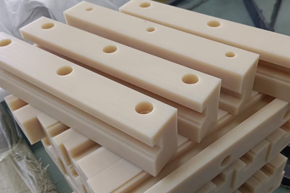
Does this wall / panel / MG engineering plastic sheet actually block the radiation the way the drawing says?
You can’t answer that with a pretty brochure.
You need tests. Real tests.
In this article we walk through the practical methods that people in radiation jobs really use, and how they fit with UHMWPE-based MG engineering plastic sheets from a manufacturer like Dongxing Rubber’s group.
Table of Contents
Gamma Attenuation Testing for Shielding Materials
This is usually the first test people do.
You take a known gamma source, put your shield sample in the beam, and measure how much dose comes out on the other side.
In practice, this test answers three questions:
- How many percent of the beam the sheet stops at a given thickness.
- What is the half-value layer (HVL) and tenth-value layer (TVL).
- Does the real performance match your datasheet and design calc.
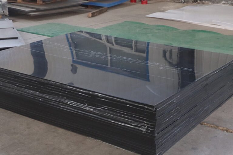
For MG engineering plastic sheets based on UHMWPE or HDPE, sometimes with fillers, you want to see:
- Stable attenuation across the energy range you care about.
- No “weird” results from poor mixing or voids.
Engineers use this test when they compare:
- Plain UHMWPE sheet.
- Borated PE sheet.
- Metal-plastic sandwich panels.
If the gamma attenuation test already looks bad, we don’t even go to the next step. The material fail at the gate.
Neutron Shielding Verification with Activation Foils
For many nuclear or isotope jobs, gamma is only half of the story.
Fast and thermal neutrons is the real headache.
Hydrogen + boron inside PE is a classic combo.
But you still must prove it works, not only say it.
So people use activation foils or neutron dosimeters:
- Put foils before and after the shield.
- Irradiate under real or near-real source conditions.
- Measure activity and convert to neutron flux.
If you sell borated MG engineering plastic sheets, this test gives you:
- Shielding factor (before vs after).
- Energy response (fast vs thermal).
- A nice plot that sales team can show in front of tough engineers.
Dose Mapping in Real Operating Conditions
Lab tests are clean and pretty.
Real facilities are not.
Loads change.
Sources move.
People push trolleys, pallets, tools, even big tanks right against the wall.
That’s why dose mapping is a key practical method:
- Place a bunch of TLDs / OSLs / film badges inside and outside the shielded volume.
- Run the source under normal or “worst case” conditions.
- Read out all dosimeters and draw a dose map.
You want to know:
- Where is the hot spot.
- Where is the cold spot.
- What is the Dmax / Dmin ratio in the room or behind the wall.
For example, imagine a small hot cell with a wall made from modular blocks and UHMWPE-based MG sheets on the inside to cut down secondary scatter.
During dose mapping you might see:
- Higher dose near a cable penetration.
- Lower dose near a corner with more overlap.
Then you adjust: add one more MG engineering plastic sheet liner, plug penetrations better, maybe change the load pattern.
Shield Integrity Scanning for Gaps and Streaming Paths
Even if the math is perfect, one small gap in the shield will ruin your day.
On site, commissioning teams often take a survey meter and “scan” the walls and joints:
- Door frames and sliding doors.
- Panel joints between modular blocks.
- Cable ducts, air vents, pipe sleeves.
- Corners where concrete and plastic panels meet.
If they see a local spike on the survey meter, that’s a streaming path.
Radiation “leak” through a tiny channel like water through a crack.
This is especially important when you use plastic shields:
- UHMWPE or MG engineering plastic sheets are easy to cut and drill.
- Installers sometimes cut a bigger hole “just to make it fit”.
- They forget to backfill with proper plugs or overlapping pieces.
So a good integrity scan becomes a sales argument:
- You can promise a “no streaming path, checked point by point” handover test.
- You can offer a yearly re-scan as a service contract, together with other maintenance work.
Customers in pharma, isotope production, NDT, or research labs like this kind of language.
It sounds like you know the job site pain, not just the catalog words.
Comparing Practical Shielding Test Methods
Below is a simple comparison you can drop straight into your blog or brochure.
| Test method | What it checks | Typical output | When to use | Main risk if you skip it |
|---|---|---|---|---|
| Gamma attenuation test | Basic gamma blocking of the material | HVL, TVL, % transmission vs thickness | When you select between different sheet materials or fillers | You may pick a material that looks strong but actually weak at your energy |
| Neutron activation / dosimetry | Neutron shielding effect, especially for borated PE | Flux reduction, spectrum change | When your source has strong neutron component | You think hydrogen is enough and ignore capture gamma and neutrons |
| Dose mapping | Real-world dose in the room / behind shield | Dmax, Dmin, dose contours | Before final handover, or after big change in load or layout | Unknown hot spots where staff stand every day |
| Shield integrity scan | Gaps, bad joints, streaming paths | Local dose peaks along walls and doors | After installation of modular shields, doors, penetrations | One tiny hole causes full design to fail safety rules |
| Periodic re-test | Long-term stability of shield and installation quality | Trending data over time | For regulated labs, hospitals, nuclear sites | Slow degradation or damage stay hidden for years |
We don’t just sell plastic sheets. We test, verify, and then keep an eye on it.
Combining Test Results with Shielding Calculations
Of course you still need design calculations.
People use point-kernel methods, Monte Carlo codes, build-up factors, all that “sharp pencil” math.
But in a modern project, the process usually look like this:
- Do the calculation with conservative data for concrete, steel, and plastic sheets.
- Choose a stack-up (for example concrete + steel + MG engineering plastic sheets as inner liner).
- Run gamma / neutron tests on the materials in the key energy range.
- Install, then do dose mapping and integrity scan.
- If data and calc match well enough, you sign it off and start operation.
If your measured dose is a bit higher than the calc, you don’t panic.
You first ask:
- Is the source really in the assumed position
- Is the load denser than the model
- Are all MG sheets in the correct thickness and density
Then you tweak: add one more layer, overlap joints, or change usage rules.
This “calc + test + adjust” loop is what serious buyers expect from a partner in high-performance engineering plastic products.
What This Means for MG Engineering Plastic Sheets Buyers
So how do you turn all this into business value for your UHMWPE & HDPE line
Here is a simple approach you can use when you talk with OEM / ODM clients, big wholesalers, or project integrators:
- Position MG engineering plastic sheets as part of a full shielding solution, not just a generic slab of plastic.
- Offer support on test planning: which methods to use for their scenario, what data you already have.
- Provide example gamma and neutron test reports in your technical pack.
- Suggest a commissioning checklist: dose mapping, integrity scan, visual check of all joints and penetrations.
- For long-term clients, sell a re-verification package every few years.
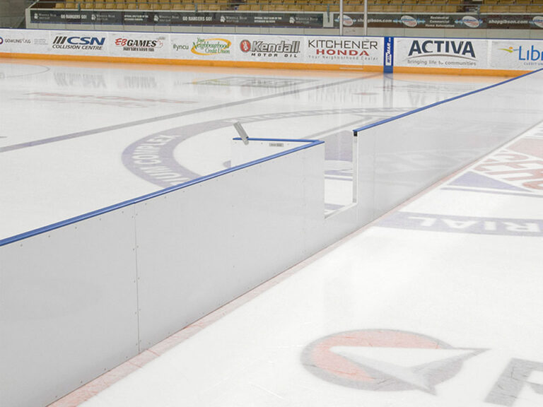
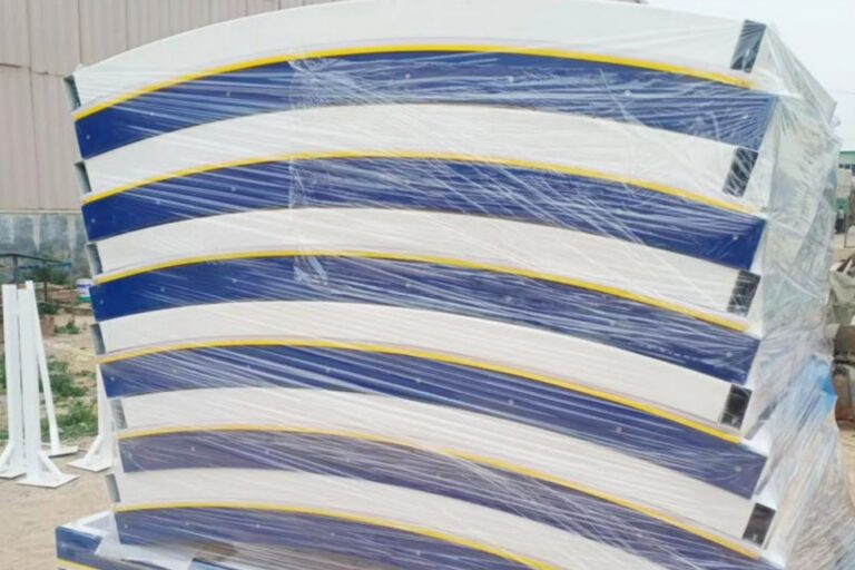
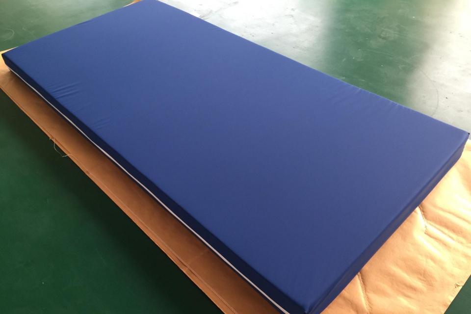
We at Dongxing Rubber focus on UHMWPE & HDPE shielding plates, ground mats, ice rink boards and MG sheets.
We help you not only pick a material, but also verify it works in your own room, with your own source.
That is how you really verify shielding performance in the field, not only in a spreadsheet.